A customer had a Cambridge Audio Amplifier A3i which had previously been repaired for not switching on past the protection.
Protection circuitry is to designed not to connect the amplifier the speakers to prevent the “Thump” on switch on AND to check various amplifier circuits safe to switch on.
The protection circuit on the A3i amplifier is as follows:
Output Over Temperature
Over Current Protection
DC Output of the amplifier output transistors
Time Delay
Mute Switch
See protection relay circuit diagram below
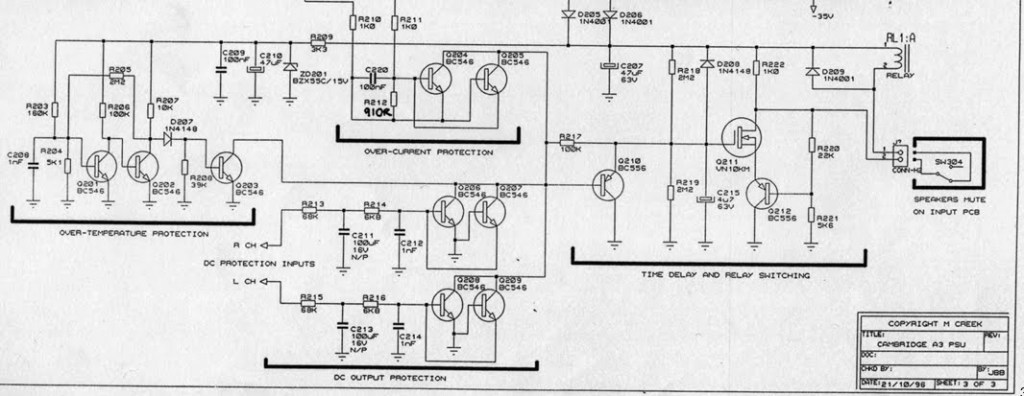
Once all 5 protection circuits pass the amplifier with switch the protection relay on connecting the speakers “Click”
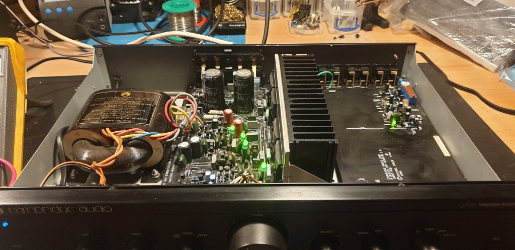
The reported problem was that the unit was powering on but the protection relay was not enabling and therefore no sound.
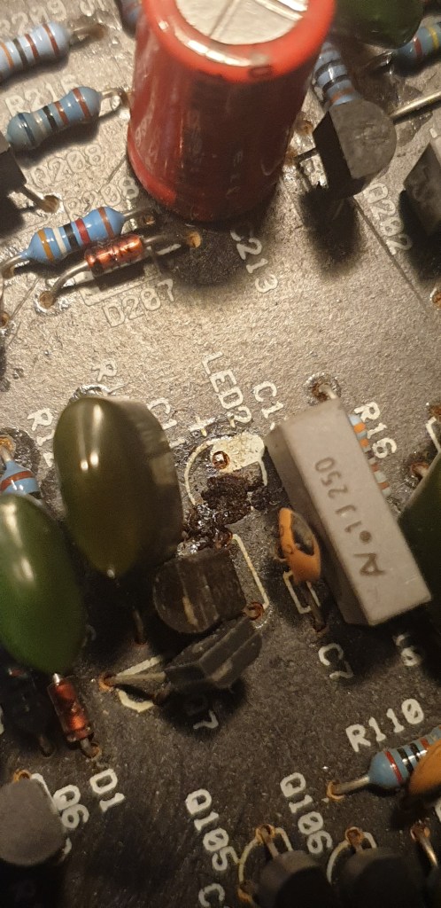
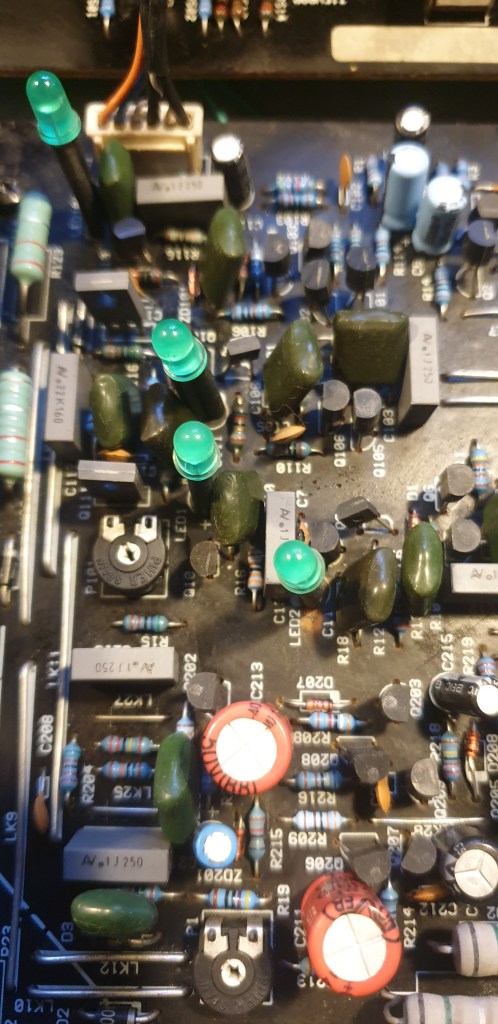
Opened up the unit. Saw that one of the Amplifier protection LEDs was off and the other was dim. Indicating an issue on the channel
Checked the various inputs into the protection system and found that the DC bias input was at -35V which is way above the 12mV that the DC bias is typically at.
Further analysis and the LED not being lit and a -35V bias for the faulty channel.
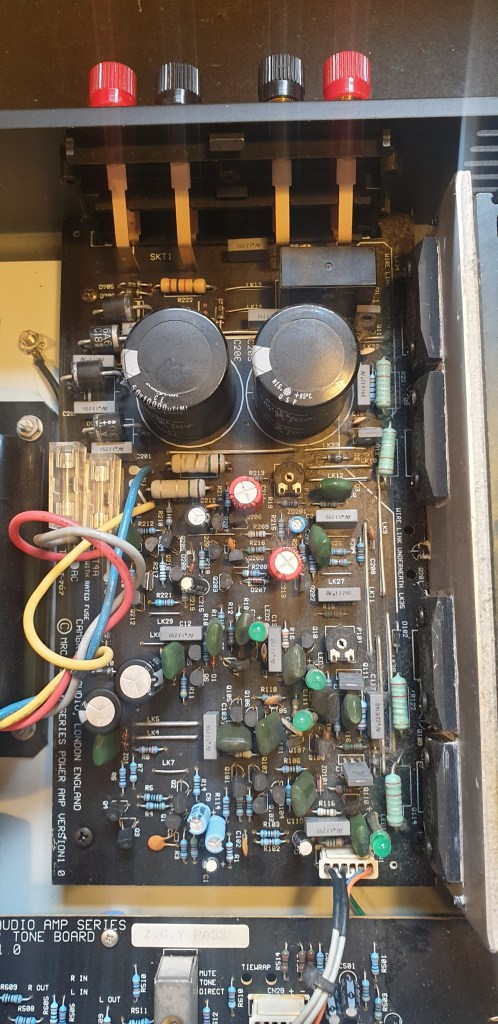
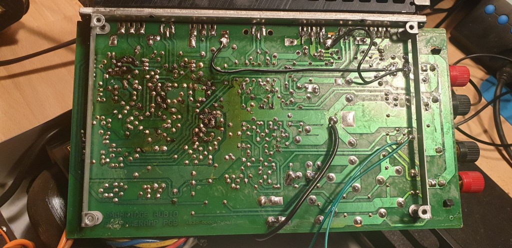
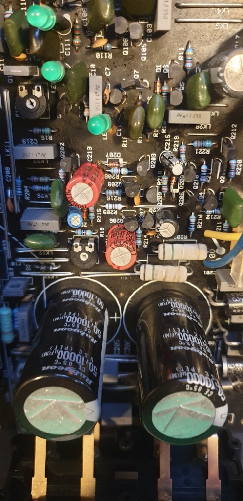
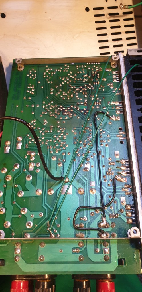
Looking further into the circuit it was found that a large amount of corrosion was present on the component side (Top) and also solder side (bottom) of the PCB.
Tope / Bottom Photos
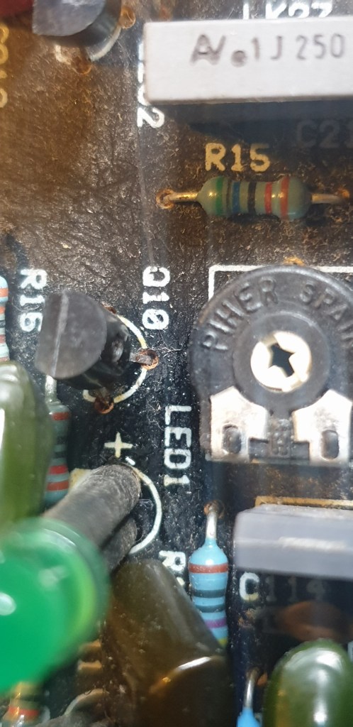
It was found that a few components had suffered damage due to corrosion.
After cleaning off as much residue, corrosion and dry solder joints.
The following components were replaced as part of the repair and also suggested servicing:
Main PSU Electrolytic Capacitors:
PART: 1189-2739-ND MFG : RUBYCON / 50USC10000MEFCSN25X50 DESC: CAP ALUM 10000UF 20% 50V SNAP TH
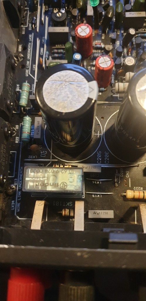
Protection Relay:
PART: 2066-40.62.9.024.0000-ND MFG : FINDER RELAYS, INC / 40.62.9.024.0000 DESC: RELAY GEN PURPOSE DPDT 10A 24V
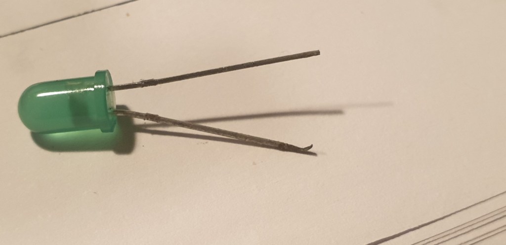
Amplifier Protection LEDs:
PART: 160-LTL2R3KGD-EM-ND MFG : LITEON / LTL2R3KGD-EM DESC: LED GREEN DIFFUSED T-1 3/4 T/H
Once the cleaning and replacements made the Unit has its output transistors DC Bias set to +12mV +/- 1mV
Then a few hours testing and its ready to be returned to the customer.
Images of the repair.

Leave a comment